sliding wardrobe doors gear

ARES2 - Kit for 2 or 3 doors High quality sliding wardrobe door system for doors up to 70kg in weight Kit contains all components needed to fit two or three sliding wooden or MDF doors Kits supplied in clear plastic box, with descriptive inserts, barcode and instructions ARES3 - Kit for 3 doors The complete sliding door system for doors up to 70kg in weight Includes high quality door gear plus decorative door edging profiles Kit contains all components needed to fit three 18mm doors Horus - Kit for 2 or 3 doors High quality 'double top' style sliding door system for doors up to 45kg in weightKit contains all components needed to fit two or three sliding wooden or MDF doors ARES 3 Joining Profile Joining Profile for ARES 3 System allows additional panels, mirrors or glass fillers to be fitted Kit includes a 1.8m aluminium profile (silver or brown) which will accept an infill panel of 18mm thick, or glass or mirrors of between 4 - 6mm thick.

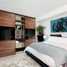
A Frame - Top Liner (optional)B Top TrackC Frame - Strike Plates (optional)D Sliding DoorsE Base TrackF Frame - Bottom Liner (optional)G End Panel (optional)
roll up garage doors arkansas Please refer to the comprehensive measuring guide on our website:
auto glass repair cathedral city Please measure carefully both the opening height and width in a minimum of three places.
hollow metal door njPlease provide the smallest measurement for the height and the narrowest measurement for the width. If the height or width measurements vary by more than 5mm we recommend constructing a simple frame using strike plates and liners which can be purchased through our website: 3. Tools & fixings you will need

Tools• Electric Drill• Screwdriver• Hacksaw (recommended 42 tpi blade to trim track sets)• Electric Jigsaw* / Handsaw*• Spirit Level• Set Square• Bradawl• Plumb Line• Metal Drill Bits (4mm diam.)• Wood Drill Bits (2mm diam.)• Wood Drill Bits (4mm diam.)• Masonry Drill Bits (8mm diam.)• Countersink Drill Bit• Tape Measure Fixings / Materials• Masonry Wall Plugs• Wall and MFC Fixing Screws• Cover Caps for Screws• Corner Blocks and/or Timber Battening (if installing end panels or interior shelving/partitions)• Packers• Sand Paper• Masking Tape 4. Constructing the frame 4.1 Planning the area IMPORTANT - Before beginning construction check all relevant dimensions carefully. Check the area for water pipe and electric cables. 4.2 Constructing a frame (optional) Constructing a frame will help with levelling, ease of fixing and will increase stability of the finished wardrobe. Strike plates and liners are available through our website in kits of 2, 3, 4, 5 or 6 pieces depending upon the size of wardrobe and your order.

Any aperture wider than 2620mm will need two floor/ceiling liners butted together.Note: For installations over carpet or where carpet is going to be laid we recommend you use the liner system. TIP - When cutting the strike plates and liners to length use masking tape along the cut lines to prevent the laminate surface from chipping. Carefully remove the tape after you have finished cutting. Check all levels before final fixing. N.B. Strike plates and liners come oversized and will need to be cut down. 4.3 Fitting an End Panel (optional) If you are not using the full width of an alcove, or constructing your wardrobe from a corner in the room, you will need to add an end panel. This can be attached to the floor, ceiling and back wall using fixing blocks, or with timber battening and screws. The end panel replaces the requirement for one of the strike plates and therefore needs careful positioning and cutting to size so that it fits flush with the ceiling and floor liners.
TIP - If you are creating a wardrobe which which will need a top panel adding (see 4.4), make sure the end panel is taller than the height of the frame by 18mm so that the top panel will fit flush with the top edge of the end panel - see top illustration. N.B. End panels come oversized and will need to be cut down. 4.4 Fitting a Top Panel (optional) If you are not using the ceiling of the room to create the ceiling of your wardrobe, you will need to add a top panel. This can be attached to the top liner, the side panel and back walls using fixing blocks, or with timber battening and screws. TIP - If you are using screws to fix the top panel to the top liner of the frame, make sure the screw ends do not protrude through to the underside of the top liner as this will spoil the appearance and may prevent the top guide track being attached properly. N.B. Top panels come oversized and will need to be cut down. 4.5 Full height End Panel and Ceiling Infill (optional)

As an alternative to a top panel, a ceiling infill panel can be used to make up the depth between the top of the frame and the ceiling of your room. This can be fixed to the top liner of the frame, the wall, end panel and ceiling using fixing blocks or with timber battening and screws. Liners (100mm width), or end panels (640mm width) cut down to size can be used to create infill panels, depending upon the height reduction required. N.B. Ceiling infill panels come oversized and will need to be cut down. 4.6 Internal fittings - vertical supports, shelves & hanging rails Vertical supports to support internal shelving must be fitted at intervals of no greater than 1200mm. Set the vertical supports and shelving behind the profile of the frame. After checking the supports are perfectly vertical they should be fixed securely to the floor, the walls and ceiling using fixing blocks or with timber battening and screws. Shelving can then be attached to the walls, end panel and vertical supports using fixing blocks or with timber battening and screws.
All interior components come oversized and will need to be cut down. 4.7 Cutting the tracks Carefully measure the width of your opening at the top and bottom. Deduct 2mm from each measurement and cut your top track and bottom track to the correct length with a hacksaw.For positioning of tracks at Section A/A please see the next step 5.2.TIP - To assist when cutting the top track insert 50mm x 38mm (2”x 1½”) wood blocks into each channel for support - see illustration below. To make it easier to mark the position for cutting and to prevent the saw blade skidding it is also advisable to wrap masking tape around the track before commencing cutting. Once the track has been cut, remove the tape. 4.8 Positioning and installing the bottom track To ensure the correct positioning of the bottom track use a plumb line from the front edge of the top track and mark three points on the bottom liner (or floor). Draw a straight line through these three points using a rule. Depending upon whether your bottom track is steel or aluminium please refer to the appropriate section below for drilling and positioning.
Position the bottom track 22mm behind the line you have marked (see illustration a). Mark on the bottom track, along the centre line where the screws will be fixed. Set the holes approx. 80mm from each end and space the remaining holes evenly at approx. 500mm intervals. Drill 4mm holes through the bottom track at the points you have marked and then mark these positions on the bottom liner (or floor) with the bottom track positioned on the line you drew in the step above. Fix the bottom track using the same method as used to fix the top track. Position the bottom track 8mm behind the line you have marked (see illustration b). 4.9 Installing the doors Note: Depending upon the material and size of your doors they can be very heavy. It is advisable to have another person to help you lift and install the doors. Install the rear door(s) first. Tilt each door as shown and fully insert the top of the door into the rear channel of the top track (A). Taking care not to damage the bottom rollers, align them with the bottom track (B) and slowly lower the door, letting the rollers snap into the track grooves.

Repeat the process with the front door(s), using the front channel and front bottom track. For multi door systems alternate the doors on the tracks. TIP - By default the bottom rollers are set to the lowest position so you may have to adjust these to raise the doors up. If the doors are set to the lowest position take care not to scratch the bottom track when testing the slide. 4.10 Checking movementMake sure the doors and tracks are positioned parallel and level. Check both doors travel smoothly along the entire width. Follow the next steps to make the final adjustments. 5.1 Steel frame - bottom roller Make sure each door sits flush with the wall and/or other doors by raising and lowering the left and right sides of the door. The door level above the bottom track can be raised or lowered by adjusting the screw on the bottom rollers, using a screwdriver. • To move the doors down - Turn clockwise • To move the doors up - Turn anti-clockwise 5.2 Steel frame - top roller