garage door closer wifi

The home automation and Internet of Things markets are heating up and many established manufacturers are trying to get an "in" by adding HA/IoT functionality to their products.Back in November, 2012, I reviewed the Hunter Fan Company's Universal Internet Thermostat and, as I pointed out at the time: ... even with its leaden physical design and poor communications architecture, the Universal Internet Thermostat could have been a fairly good product, but here we have a product that was apparently developed by blinkered engineers who don't grok the 'Net.The central issue I had against Hunter's product was that it was isolated from any and all other connectivity and integration so it's value was severely limited. It would seem that consumers agreed with me because in July last year Hunter began an buy-back campaign and took the product off the market. With examples such as this you'd think that other companies with similar market ambitions would wise up but apparently this is not the case.

I recently tested the MyQ Garage ($129.99) from Chamberlain, purveyors of fine garage door gear, which works with your garage door opener and not only opens and closes your door from anywhere using a smartphone app but also notifies you when the door's state changes.The MyQ setup involves installing a sensor on the door that detects whether the door is open or closed and transmits that data to the MyQ WiFi Hub. The Hub itself is a small box that mounts on the ceiling next to the door's controller and using Chamberlain's free iOS or Android app on your smartphone or iPod you configure it to use your WiFi network.You then pair the Hub with your garage door opener (a large number of other manufacturer's openers are supported along with all of Chamberlain's products). I had a lot of trouble getting this step to work and the solution was to rotate the hub 180 degrees which apparently unblocked radio communication between the opener and the Hub. I'm told a firmware update will fix this but I'm surprised that a glaringly obvious problem like this got past QA.

you can be notified when the door is opened or closed, open or close it, and see how long ago the door changed status. The MyQ also makes very loud warning beeps before opening or closing the door.That's it and that's the problem: It's a closed system. You wind up with yet another app you have to be running to have control a piece of your house and you can't integrate the MyQ system with any other home automation systems although an HA system that can parse emailed alert messages (which MyQ can generate as well as push notifications) could understand the status of the door and generate alerts or do whatever you please (except open or close the door). can cause a long delay between you issuing a command and the door doing what you want.It would be so easy for Chamberlain to make this product what it should be but we'll see if they do. I'll give the Chamberlain MyQ Garage a rating of 2 out of 5. then follow me on Twitter, App.net, and Facebook. Join the Network World communities on Facebook and LinkedIn to comment on topics that are top of mind.

When I was little, I used to push the garage door button from inside the garage and then run out the garage while it's closing... carefully jumping over the sensor so I don't trip the safety mechanism. It was easy back then and a little fun.
magnetic door lock tutorialBut nowadays, not so much.
patio sets for sale reginaThere are times when I wish I had a way to close (and open) the garage door remotely and preferably with something I always have on me... my mobile phone!
66 chevelle door panels for sale So this past Christmas, I looked into building something so I could use my smartphone as a garage door opener.
replace door lock 2003 honda civic
I've read about the Arduino and Raspberry Pi platforms before that I believed would accomplish the task and, ultimately, I decided on the Raspberry Pi. The Arduino platform after some research and cost analysis would have cost more than the Raspberry Pi!
sliding wardrobe door closerThat wasn't something I was expecting since the Raspberry Pi is more robust and a full-blown mini-Linux computer.
kitchen cabinet doors 600 x 720The possibilities are really endless.
victorian door hinges sale A wifi Raspberry Pi connected to a 2-channel relay connected to my actual garage door remote allows me to open and close my garage door with just a browser on my smartphone. After only writing software for many years in web development, creating something that interacts with the real world was a special kind of excitement for me when I saw it work for the first time.

Below I'll go through the steps and the issues I ran into while working on this project. Below is a list of the parts I gathered together to get started. Prices will most likely not be same. Total cost: $63 since I had a few of the needed parts already. I followed this guide to setup the SD card with NOOBS and bootup the Pi for initial setup. Raspberry Pi Quick Start Guide Setting up the Pi is pretty easy. Just hookup the HDMI cable, usb keyboard and mouse, plug in the SD card prepared in step 2, and finally turn on the Pi by plugging in the micro-USB power supply. This should bootup NOOBS and step you through the process to install an OS. The one you want for this project is Raspbian. Complete the Raspbian setup and you should have a working Pi at the end. It's at this step that I encountered my first problem. I used the keyboard and mouse I had from my main PC rig, a Logitech G110 keyboard and a Logitech G9 mouse. After NOOBS booted up, I found I couldn't type or control the mouse.

The problem turned out to be the USB ports on the Pi doesn't provide enough power for the keyboard and mouse. You can get around this issue by using a powered USB hub. You can skip this step if you're going to leave the Pi connected with ethernet cable. In fact, I recommend skipping this step until the end to simplify things. I didn't want the Pi to be tethered by an ethernet cable so I proceeded to try and set it up with the USB wifi dongle. This turned out to be probably the hardest part of the project. I followed a bunch of guides I found but none of them worked for me. It's not that the dongle wasn't supported by Raspbian, but I couldn't get it to connect to my wireless router. After much headache and tinkering around, I finally fixed the problem. You can read about the details in my wifi setup guide.The new version of Raspbian includes a new version of a wifi manager that worked flawlessly for me and the above step wasn't necessary. Simply run the Raspbian GUI with startx then find the wifi manager icon in the upper-right corner and set it up for your wifi AP. Pretty straightforward with a GUI.

After using this setup for a few weeks, I found the Pi to be inaccessible after a period of inactivity. This turned out to be a power savings feature where the wifi component is turned off. I did the following to disable this feature: What makes the Raspberry Pi so interesting to me are the GPIO pins which allow the Pi to communicate and control other peripherals. I found this excellent guide to get a basic understanding of the GPIO. My first test with the pins was to simply connect a LED I had lying around and see if I could get it to light up. LEDs generally have 1 leg which is longer than the other. The longer leg should be the + (positive) connection. If the LED doesn't have a visible difference in the leg lengths, then you can look at the top of the LED and you should see 2 small pieces of metal. The smaller side is the + connection. Here's a good diagram. Start by connecting a jumper wire to GPIO pin 1 for the 3.3v power and another wire to the GND at pin 6.

This should light up the LED. Ok, admittedly, that's not terribly exciting. It's just a light. Next, unplug the jumper wire from pin 1 and connect it to pin 7 which is GPIO4. The LED should be unlit for now. To control the GPIO ports, there are a ton of different choices. Just google for Raspberry Pi GPIO but I started with this wonderful framework called WebIOPi. Follow the WebIOPi installation guide and run this: That should start the webiopi server on port 8000. You can then access the webiopi page in a browser at http://192.168.1.60:8000. Of course, replace 192.168.1.60 with the IP of your Pi. You should see a GPIO Header link on the main page. Click that link and you will be able to control the GPIO using a web UI which looks like the board header. Click the 'IN' box to the left of GPIO4 to toggle that to say 'OUT'. Then try clicking on the box to the right of GPIO4 with the number 7 in it. If everything's working then you should now be able to on/off the connected LED.

Toggling the LED on/off was super exciting for me. It was the first time I had built anything on a computer that could interact with the real world. The Internet of Things as they say. For better or worse, it's coming and probably sooner rather than later. Now it's time to replace the LED with the relay. Remove the LED from the jumper wires and reconnect the wires according to this drawing below. It was at this point that ran into my next problem. Every time I connected the relay and switched GPIO4 to 'OUT', the Raspberry Pi would crash and I'd have to unplug/reboot it. It took me awhile to figure out that the power supply I was using wasn't supplying enough power for everything. Apparently, powering the relay pushed it over the edge. The power supply I was using was from an old Motorola smartphone that was rated to only output 750ma. After I switched that out to another power supply I had lying around with 1850ma, I no longer had stability issues with the Pi. You can test your connections now by going back to the WebIOPi page and toggle GPIO4 on/off and you should be able to see a small light on the relay respond accordingly.

If you do, then that's a good sign. It means you are able to control the relay to open and complete a circuit. For this step, you can either run wires to the actual garage door opener button that's in your garage, or use a spare garage door remote. Since I planned on leaving the Pi indoors where I have easy access to it, I chose to hook it up to a remote. I pried open the remote casing and studied the circuit board a bit. The first thing I did was to test if I could activate the remote without actually pressing the button so I shorted these 2 points by touching them with a wire. I heard the sounds of the garage door creaking open. So, theoretically, I should be able to wire that to the relay and have the relay open/close the circuit. Boistered by this knowledge, I looked at how I could solder 2 wires to the circuit and noticed that the remote was gracious enough to leave some extra holes that runs in serial with the actual button. Then I soldered 2 wires to the remote and connected them to the left and middle connections on the relay like this below.
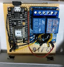
Now toggling GPIO4 in WebIOPi should actually open and close your actual garage door. You might notice when you're doing this that the garage door only activates when the signal from GPIO4 is off. The relay I bought, the Sainsmart 2-Channel Relay and if what I've read is correct, most other relays work like this. When the signal is ON, the relay is open which means the remote won't activate. When the signal is OFF, then the relay is closed and the circuit is complete which should activate the remote. Keep this bit of info in mind when we work with setting up the WebIOPi code later. ** UPDATE (2/17/15): Take a look at Node-GaragePi if you prefer Node.js to Python and how you can replace the battery in the garage remote. It is setup with this file structure below: Download and extract the GaragePi zip file to /home/pi/garagepi. Or you can also clone it from Github: WebIOPi by default is setup with a login and password. But I only plan on using this when I'm on my local wifi network so I opted to remove the password protection completely.