magnetic door lock tutorial

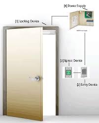
Category: Arduino, Video Tutorials, Tutorials Are you are the type of person that can never find their keys or are you constantly running into your building wasting those designated “elevator minutes” on having to rummage through your bag to find your ID card to get through security? Well if that sounds familiar to you from your own experiences or someone that’s close to you comes to mind, then we have just the remedy for you. In this tutorial we are going to show you how to control a magnetic door lock using RFID technology. But first let's have a look at relays and RFID readers. RFID stands for Radio Frequency Identification. This type of technology uses radio signals to transfer and receive data. The transmitters are called tags. Each tag has a unique ID code that serves to distinguish one tag from another. When you put the tag close to an RFID reader, the module picks up the radio signal from the transmitter and reads it. For more information on RFIDs you can refer to these tutorials:
A relay is just a like a regular switch but controlled electronically. Which means that instead of activating it manually, we use an electric signal to open or close the switch. Usually relays are used in circuits that work with high voltages, or alternating current (AC). We can identify two different types of relay connections: normally opened (NO) and normally closed (NC). In this figure we see the basic mechanism of a normally open relay. When switch S1 closes, it energizes the coil which generates a magnetic field. This magnetic field attracts switch S2, forcing it to close and letting current flow in the second circuit to feed the load. Note the voltage difference between the low current circuit and the high current circuit. This means that we can use a component like an Arduino UNO, which can only provide a maximum of 5V, to control a circuit that requires more than 5V. This diagram shows the basic mechanism of a normally closed relay. In this circuit S2 is always closed thus feeding the load with current while S1 is opened.

When S1 closes, it energizes the coil which generates a magnetic field. This magnetic field attracts S2, forcing it to open. When this happens the high current circuit stops feeding the load with current. So in other words, an NC circuit is the opposite of an NO circuit. The diagram below shows how these two circuits are implemented in a relay: The numbers represent the physical pins of the relay. Therefore, when current flows between pins 2 and 5, the coil energizes creating a magnetic field that will attract the switch. Pin 1 is referred to as a common, this pin is attached to the high voltage power supply that will feed the high current circuit. Pin 4 is used for NC connection, while pin 3 is used for NO connection. Below is another representation of this circuit: In this project the high current circuit is the magnetic door lock which operates at 12V DC. The low current circuit is the Arduino UNO which operates at 5V. You will need the following items for this project:

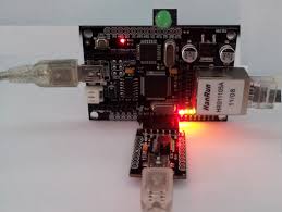
WiringConnect 5V and GND from the Arduino UNO to the power rails of the protoboard: Connect the RFID reader as follows: The negative side of the buzzer connects to pin 3 of RFID reader, and the positive side to 5V: Buzzer Connection to Pin 3 Connect cathode side of green LED to pin 6 and cathode side of red LED to pin 5 in the Arduino UNO. Then connect the anode side of each LED to a 330 ohm resistor. The other end of each resistor is connected to ground.
linear digital garage door opener Connect the relay to the Arduino UNO as follows:
garage door repair huntington ny Relay Connection to Arduino UNO
garage door springs for sale calgary
Now connect the relay to the magnetic door lock and power supply: Red Wire of Lock Black Wire of Lock GND of Power Supply Upload this code to find out the code of your RFID tag. *Note: You need to disconnect the wire going to pin 0 of the Arduino UNO before uploading the code. Once the code is uploaded you can connect it again. This code serves to find out the ID code of our tag. The program sets the baud rate to 9600 bps and constantly checks if there is incoming data from the RFID reader.
auto glass repair troy miWhen a tag gets close to the reader, the Arduino UNO stores the ID code in a buffer to read it and print it on the serial monitor.
sliding glass doors miami fl Upload this code to control the magnetic door lock with your RFID tag.
barn door hardware victoria
Once again, you need to disconnect the wire going to the Arduino UNO before uploading the code. Here we assign pins 7, 6, and 5 from the Arduino to the relay, green LED, and red LED accordingly. Then we create a buffer (tag) that stores the ID code of our known tag. Next we create another array (input) that will hold the ID code of the tag that will be presented to the RFID reader. Lastly we declare the variable count as integer to go through each of the characters in the arrays, and initialize it to zero.
windows and doors cebuWe also declare the variable flag as boolean to check if the string comparison between tags is equal or not. The variable is initialized to zero (false). Here we set the baud rate to 9600 bps, and set the relay and LEDs as outputs. In the For Loop we constantly check if a tag has been presented against the RFID reader. If the case is true, we reset the counter to zero so that each time there is new incoming data in the serial buffer we point to the very first character of the ID number.
Then we use a While Loop to store the incoming data in the input buffer. This If Statement serves to check if the count has reached 12, which is the size of the ID number. When the count reaches 12 we reset count to zero and set flag to one. Then we use a While Loop to compare character by character the input buffer to our known tag number to see if they are the same or not. If they are equal we set flag to 1, otherwise we set it to 0. This If Statement is used to check if flag is equal to one. If the case is true, then we turn on the green LED and the relay for five seconds. This will make the relay open the switch from the high current circuit, which will cause the magnet to shut off, thus, granting us access to the room. If flag is not equal to 1, then we turn the red LED on for three seconds to indicate that the tag presented to the RFID reader does not match our known tag. The last part of the code is used overwrite whatever value the input array is storing with the value “F” throughout the array.