magnetic door lock circuit diagram
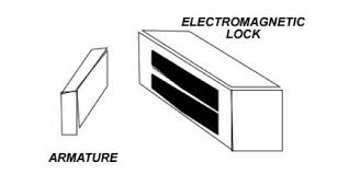
Basic Magnetic Door Lock SystemElectromagnetic LocksElectromagnetic locks are widely used in commercial and industrial applications. The lock is usually mounted on the header above the door and the armature is usually mounted on the door (see drawing below). Different arrangements can be made for inswing or outswing doors, and different holding forces, monitoring switches, and other variations and options are available. In this article I will discuss only the basics. As with any locking system, use of electromagnetic locks may be restricted by local authorities such as your local building inspector and/or fire marshall. It is wise to check with these authorities before installing an electromagnetic lock. System OverviewTo install the most basic electromagnetic locking system on an out-swinging hollow metal commercial door and frame you need the following: The electromagnetic lockA way inA way outA power supply The electromagnetic lock is an appliance. It unlocks when you shut off the power.

Therefore the means of entry and egress will be swtiches of some form or other. Means of entry could be: A key switchAn access control device like a card reader or keypad A remote as for a garage door openerYour choices for means of egress are limited by national, state and local life safety code. They could be: A mechanical push bar with a mechanical switch insideA pushbutton with pneumatic time delay clearly marked "Push to Exit" right next to the doorAn exit sensor with redundant pushbutton Your local Authority Having Jurisdiction (AHJ) may require that your power supply be connected to the building fire alarm so that in the event of an alarm, the panel can unlock the electromagnet. In any case you need a power supply with sufficient capacity to power your electromagnet. /A simple electromagnetic locking system by Securitron might consist of: 1 each M62 electromagnetic lock1 each BPS-24-1 power supply1 each DK-26SS keypad1 each XMS exit sensor1 each EEB2 redundant exit pushbutton View these products at

: /Simple Wiring Diagram
front door designs in kerala style How to Lay Out a Master Key System ScheduleLearn the basic principals of the master key system so that you can communicate intelligently with your security professional.
interior sliding doors sacramento Security & Monitoring ElectronicsTouch Bar Release Devices for Magnetic LocksA review of popular mechanical and electronic touch bars used to release electromagnetic locks for egress.
patio furniture for sale lawrence ks How to Adjust Your Door CloserThe theory and practice of door closer adjustment, with steps and detailed instructions to adjust the swing of your hydraulic door closer.
garage door parts douglasville ga
Comments Go to last comment
ibm sales salary glassdoor View our extensive library of already created product wiring diagrams to assist with your product installation.
outdoor fire pit lawrence Don't see what you're looking for?
french door refrigerator 33 inch widthThe Securitron Technical Services Department is able to create additonal wiring diagrams to meet your needs free of charge and in a timely manner: Single Door System Wiring Diagrams Single Door Controlled Egress Wiring Diagram - #01 Single Door Digital Entry Wiring Diagram - #10 Single Door DK 26 With Door Prop Alarm Wiring Diagram - #15 Single Door DK1-11 XMS DT-7 Wiring Diagram - #20 Single Door DK-26 Remote Release Wiring Diagram - #14

Single Door DK-26 UNL-24 And DT-7 Wiring Diagram - #18 Single Door DK-26 Using The Hard Code To Toggle Lock Off And On Wiring Diagram - #17 Single Door Exit Delay System Wiring Diagram - #04 Single Door Exit Delay System With Movement Initiate Wiring Diagram - #05 Single Door Key Entry With UNL-24 Wiring Diagram - #21 Single Door Key Switch Entry And Motion Detector Wiring Diagram - #16 Single Door Monitored Access Free Egress Wiring Diagram - #03 Single Door Restroom Park System Wiring Diagram - #25 Single Door Restroom With UNL-24 Wiring Diagram - #24 Single Door Secure Room Digital Entry And Egress Key Override Wiring Diagram - #19 Single Door UNL-24 And Point To Point Monitoring Wiring Diagram - #02 Single Door User Code LockOut With DT-7 Wiring Diagram - #22 Single Door With Door Prop Alarm Wiring Diagram - #09 Two Door System Wiring Diagrams Two Door Entry Hard Code Used To Turn User Code On And Off Wiring Diagram - #23

Two Door Entry With Day Timer Wiring Diagram - #08 Two Door Entry With DT-7 First Man In Option Wiring Diagram - #12 Two Door Interlock Normally Locked Wiring Diagram - #11 Two Door Interlock Normally Unlocked Wiring Diagram - #13 Two Door Interlock With Key Overide Wiring Diagram - #06 Three Door System Wiring Diagrams Three Door Interlock Wiring Diagram - #07 The main aim of the work undertaken in this paper is to sense the correctness of a secret code using the Arduino technology. When the correct code is entered through keypad, it lights a green LED in addition to operating a small solenoid which when powered, will strongly attract the metal slug in its center, pulling it into place, when the power is removed, it is free to move. ATmega168 is widely used because it supports wide range of system development tools such as C Compliers, Macro assemblers, Program Debugger/Simulators, In-circuit Emulators and Evaluation Kits . Its features includes: 23 general purpose I/O lines, 32 general purpose working registers, three flexible timer/counters with compare/capture/PWM mode, a SPI serial port, 16K bytes of in-system programmable Flash with Read-while-Write capabilities.

512 bytes of EEPROM and 1K bytes SRAM. In Idle mode CPU stops working while allowing the SRAM, timers/counters, USART, SPI port and interrupt system to continue functioning. It also has 6 channel 10-bit ADC, a programmable watchdog timer with internal oscillator .GNDGround voltage for the microcontroller chip.PORT B (PB7:0) Port B is an 8-bit bi-directional I/O Port with internal pull-up resistors. As Inputs, Port B pins that are externally pulled low will source current if the pull-up resistors are activated.Depending on the clock selection fuse settings, PB6 can be used as input to the inverting oscillator amplifier and input to the internal clock operating circuit Depending on the clock selection fuse settings, PB7 can be used as output from inverting oscillating amplifier .PORT C (PC5:0) Port C is a 7-bit bi-directional I/O port with internal pull-up resistors. As inputs,Port C pins that are externally pulled low will source current if the pull-up resistors are activated .PC6/RESET :If the RSTDISBL register is programmed, PC6 is used as I/O pin.

Behavior of PC6 is different from other Port C pins.If RSTDISBL is not programmed, PC6 can be used as a Reset input. A low level on this pin for longer than the minimum pulse length will generate a reset even without the clock signal. Shorter pulses are not guaranteed to generate a Reset .PORT D (PD7:0)Port D is an 8-bit bi-directional I/O port with internal pull-up resistors. As inputs,Port C pins that are externally pulled low will source current if the pull-up resistors are activated. The Port D pins become tri-stated if the reset condition become active, even if the clock is running .AVCC AVCC is the supply pin for the A/D Convertor, PC[5:0]. It should be externally connected to VCC, even if the ADC is not used. If the ADC is used it should be connectedto VCC through low pass filter AREFAREF is an analog reference pin for the A/D convertor.XTAL1 It is an input to the inverting oscillator amplifier and the internal clock circuit.XTAL2It is an output pin from the inverting oscillator amplifier.