craftsman garage door opener short
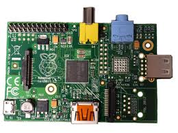
Several months ago our Craftsman garage door openers stopped responding to our remotes. I tried everything I could think of to fix this problem, short of buying anything new. Garage door opener parts are expensive, to the point buying new openers is a better option. After much research I found out that RF interference was the issue. No new remote or logic board was going to solve the issue, even getting new openers wouldn’t solve the issue. By knowing the wall switches work by simply closing the circuit I set out for a wireless solution that we could control from our iPhones. I wanted to try my hand at an Arduino, but getting WiFi to one isn’t cheap. I then discovered the Raspberry Pi had programmable pins. Getting wireless to the Pi was nearly $80 cheaper, plus it allowed me to leverage languages I already knew. I soon placed an order on Amazon for all my parts. Don’t forget (assuming you don’t have these lying around): After getting the parts in I wrote a quick node.js app that serves a single page and also has a 2 backend requests to open each garage.

The regular wall switches that came with the openers which are right next to each other, then a separate set of switches wired in another part of the garage. I went to Lowes and got some Alarm Wire (it has 4 wires inside of it), this made me only have to make one run from the Pi. I just connected my wires to the back of each wall switch using the COM and NO ports from the relays. It doesn’t matter how these are connected as you are just completing the circuit. I used this guide in my plans for this project. I have open sourced the node.js app at brentnycum/garage-node. I have also open sourced the iOS app at brentnycum/garage-ios, in order to put this on your device you need an iOS Developer Account from Apple. I ended up creating my own fork of pi-gpio to handle using the additional GPIO pins on the Raspberry Pi Model B Rev 2.0 that I used, as I soldered the relay to the board instead of using the pins. The wiring above matches my node app. To get the node.js app from Github you can either choose to download the zip file, or you can use the simple command.
Once you have the code on your Raspberry Pi, move into the app’s directory and run the npm install command to install the dependencies. npm is the node package manager. After all the dependencies are installed you can run the app. Once it’s running you will be able to point your browser to your Raspberry Pi at port 3000 (ie http://192.168.1.105:3000). Be sure to change the config.js file if you are using any different pins.This instructable explains how I setup a Raspberry Pi to open my garage door using a smarthphone. While this has been done before, I thought I'd post my solution. This was my first hardware project and instructable ever and I'm sure I made some mistakes. So, when you find one let me know! Project Overview: What we will be doing is turning the Raspberry Pi into a small web server. When you access the webserver from your browser of choice, you will have a big button that triggers the garage door via a relay. We will wire a very basic circuit to the Pi's GPIO pins and upload a website that triggers the circuit.

When the relay is triggered, it closes the circuit hooked up to the garage motor and opens the garage.Why would anyone want to do this? Well, my garage door opener was broke and this was cheaper than replacing the other system. As an added plus though, you could wire up additional sensors and be able to make sure your garage is closed remotely if your were so inclined.Shopping List: I consider myself pretty cheap, and I tried to keep the costs minimal. All of the items are available on prime. 1.) Raspberry Pi - Model A - $32 2.) Wifi Adapter - $10 3.) PSU - $5 4.) 5v Relay - $6Total: $53.00 You will also need an sdcard >= 2GB and some wires, but I had extra of each.Step 1: Install and Optimize Rasbian (for our purposes)Show All Items This first step is to install an operating system to your rpi. I'm a bit of a debian fanboy, and had an extra 2GB sdcard, so I went with a shrunk version of Wheezy. On Ubuntu, I used gparted to format to fat32, and dd to write the img. After you install the OS, plug in a usb keyboard and hook up the raspberry pi to a monitor.

Assuming you are using Wheezy, on the first boot rasp-config will automatically run. You should use this tool to stretch the parition and enable ssh (under the advanced menu on newer versions I believe). After I installed my img, I also removed the GUI to free up some space. (If you have a large SD, you can skip this.) To do this type these commands:$ sudo apt-get remove --purge x11-common$ sudo apt-get autoremove This removes all packages that depend on X11 which is pretty much all of the GUI.Hardware components:Adafruit HUZZAH ESP8266 Breakout×1Adafruit Magnetic contact switch (door sensor)×2Tolako 5v Relay Module for Arduino×130Pcs 2 Pole 5mm Pitch PCB Mount Screw Terminal Block 8A 250V×1Vktech 5pcs 6x8cm Double-Side Prototype PCB Universal Printed Circuit Board×1TOOGOO(R) 75 x 3mm Red Green Yellow Assorted Color LED Light Emitting Diodes×1Resistor 10k ohm×1Resistor 330 ohm×2Generic Premium External Power Supply 5v 1A 2A (1000mA - 2000mA) AC/DC Adapter×122AWG Wire/footI used 10 feet of

CAT 5 instead.×30Pocket Solder- 60/40 Rosin Core 0.031" diameter×1Cable tie mounts Used to guide contact switch wire down garage door opener track×6#6 x 1/2 panhead sheetmetal screwScrews for case lid×4Velco 1" x 1" squaresUsed to mount case to garage door opener×4Software apps and online services:Arduino IDEopenHABmyOpenHABHand tools and fabrication machines:Adafruit USB to TTL Serial Cable - Debug / Console Cable for Raspberry PiSoldering iron (generic)Hot glue gun (generic)3D Printer (generic)Multimeterwire stripperI created this project for a couple of reasons; one, I got tired of trying to get the built in garage door openers in my vehicles to work with both of my garage doors. Second, was that nagging question "Did I close the garage door?". Now I can get that question answered with a couple of taps on my smart phone. Also, the device will send me an openHAB notification to my smart phone if the garage door is left in the "AJAR" or "OPEN" position for longer than 15 minutes.
The project consists of a HUZZAH, relay, power supply, resistors and LEDS. The HUZZAH connects to your local WIFI and runs a small web server that responds to simple http GET/POST requests that will be sent to it via openHAB. The relay works just like your existing wired garage door switch to activate the opener except for it's controlled over WIFI via the HUZZAH. The LEDs are there to provide you status information. The red LED flashes if the garage door is not in the open or closed positions. The yellow LED flashes constantly until connection to the WIFI is established. It will also flash briefly every time a valid request is sent to the web server. In this writeup I will cover building and installing the garage door opener project. I will not cover installing and configuring openHAB, there are plenty of articles on the web that cover that. /adafruit-huzzah-esp8266-breakout/assemblySetup Arduino IDE to support the Adafruit HUZZAH. /Build the garage door opener circuit on a PCB board.
Started by hot gluing the relay down to the PCB in the upper left corner and then add the HUZZAH by soldering one or two pins to the PCB to hold it in place.Relay position on PCBRelay and HUZZAH positioning on PCBAdd the LEDs they need to placed as shown to match up with the 3D printed case design provided. Install them so the bottom of the LED is about an 1/8 of an inch above relay. That way they will fit neatly in the holes in the case lid. LED locationInstall LEDs so the bottoms are 1/8 above the relayAfter the LEDs add all other components and solder them in place with the connections shown in the images. To make the circuit connections use small pieces of stripped CAT-5 cable wire. I find trying to make the solder flow from one solder point to another just leads to large blobs of solder. I also used an old computer CD audio cable to connect the relay. Physical layout of components on PCB Physical circuit paths on PCB Circuit paths on PCB Layout of components on PCB Before installing the device on your garage door you should get openHAB up and running.

Test all the functions of the device thru openHAB before installing. NOTE: if you want openHAB to send you notifications like the one in the rules file you must use openHAB 1.8 or newer.Install the open and close contact switches. If you have a Craftsman or Chamberlain screw drive garage door opener you can use the 3D printed mount designs provided. I suggest using hot glue for all the glueing. Hot glue dries fast and can easily be removed if you need to reposition the mounts or contact switches. Start by gluing one of the contact switch magnets on the the trolley. Slide both mounts onto the track from the motor end. Close the garage door and position a mount above the trolley. Glue one of the contact switches on the mount with no more than an 1/8 gap between the switch and the magnet on the trolley. Use a multimeter to measure the resistance across the switch leads to verify that it reads closed. Hot glue the mount in place on the rail using a small amount of glue. It's my experience that the magnet and the switch need to be slightly offset for the switch to read closed as seen in the images.

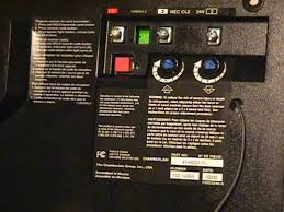
Open the garage door all the way open and repeat the process. Run wire from the contact switches to the back of the motor using cable tie mounts to keep wire from getting tangle in the trolley.Notice the gap and offsetOpen contact switch. Notice the gap and offsetCloseup of the open contact switch mountCloseup of the open contact switchCable tie mount installed on the rail. Cross section of Craftsman and Chamberlain screw drive garage door trackChamberlain door control connector screws 1 and 2Craftsman door control connector orange and white on leftA few screen shots of openHAB on my iPhone.openHAB notificationopenHAB door status and controlFuture enhancementsLook at using the Adafruit HUZZAH feather. The first version of this project was built using just a ESP8266-12. But by the time I added a buck converter, reset and flash buttons the cost was a lot more then then HUZZAH. It looks like uploading code to the feather is easier than the HUZZAH and I can use a standard USB cable to power the device.

Read moreMike Mackes ContactNoah Mackes High School Student with a passion for engineering and just building stuff. Planning on pursuing a degree and career in Engineering.ContactDid you replicate this project? Think it could be improved? Tell us what you think!Similar projects you might like Full instructionsA water bottle which can keep track of you water intake and reminds you to take enough water.Arduino Powered Water Bottle I decided to to try to get Alexa to turn on and off my gas fireplace. The fireplace had no internet control built in but rather used a RF...Alexa Activated Fireplace 4 Full instructionsI modified a Blynk-controlled car using Adafruit Feather 32u4 Bluefruit LE. I used the Accelerometer widget of Blynk.Blynk Controlled Car using Accelerometer 1 ProtipEver wish you could use BNC cables or probes with the XMEGA Xprotolab?XMEGA Xprotolab Breakout Board Full instructionsWearable for monitoring the health condition of patients who have suffered or are in risk of having a cardiac arrest.